Evoked Potential Studies
These tests evaluate the integrity of visual, somatosensory, and auditory nerve pathways by measuring evoked potentials-the brain’s electrical response to stimulation of the sensory organs or peripheral nerves. Evoked potentials are recorded as electronic impulses by surface electrodes attached to the scalp and skin over various peripheral sensory nerves. A computer extracts these low-amplitude impulses from background brain wave activity and averages the signals from repeated stimuli.
Three types of responses are measured:
Visual evoked potentials, produced by exposing the eye to a rapidly reversing checkerboard pattern, help evaluate demyelinating diseases, traumatic injury, and puzzling visual complaints.
Somatosensory evoked potentials, produced by electrically stimulating a peripheral sensory nerve, help diagnose peripheral nerve disease and locate brain and spinal cord lesions.
Auditory brain stem evoked potentials, produced by delivering clicks to the ear, help locate auditory lesions and evaluate brain stem integrity.
Purpose
To aid diagnosis of nervous system lesions and abnormalities
To assess neurologic function
To monitor comatose patients and patients under anesthesia
To monitor spinal cord function during spinal cord surgery
To evaluate neurologic function in infants whose sensory systems can’t be adequately assessed.
Patient Preparation
Tell the patient that this group of tests measures the electrical activity of his nervous system. Explain who will perform the test, where it will take place, and that it usually lasts 45 to 60 minutes.
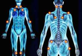
Tell him that he’ll sit in a reclining chair or lie on a bed. If visual evoked potentials will be measured, electrodes will be attached to his scalp; if somatosensory evoked potentials will be measured, electrodes will be placed on his scalp, neck, lower back, wrist, knee, and ankle.
Assure him that the electrodes won’t hurt him. Encourage him to relax; tension can affect neurologic function and interfere with test results.
Have him remove all jewelry and other metal objects.
Procedure And Posttest Care
Position the patient in the reclining chair or on the bed and tell him to relax and remain still.
Visual evolred potentials
Electrodes are attached to the patient’s scalp at occipital, parietal, and vertex sites; a reference electrode is placed on the midfrontal area or ear.
The patient is positioned 3′ (1 m) from the pattern-shift stimulator.
One eye is occluded, and the patient is instructed to fix his gaze on a dot in the center of the screen.
A checkerboard pattern is projected and then rapidly reversed or shifted 100 times, once or twice per second.
A computer amplifies and averages the brain’s response to each stimulus, and the results are plotted as a waveform.
The procedure is repeated for the other eye.
Somatosensory evolred potentials
Electrodes are attached to the patient’s skin over somatosensory pathways-typically the wrist, knee, and ankle-to stimulate peripheral nerves. Recording electrodes are placed on the scalp over the sensory cortex of the hemisphere opposite the limb to be stimulated. Additional electrodes may be placed at Erb’s point (above the clavicle overlying the brachial plexus), at the second cervical vertebra, and over the lower lumbar vertebrae. Midfrontal or noncephalic electrodes are placed for reference.
Painless electrical stimulation is delivered to the peripheral nerve through the electrode. The intensity is adjusted to produce a minor muscle response, such as a thumb twitch on median nerve stimulation at the wrist.
Electrical stimuli are delivered 500 or more times at a rate of five per second.
A computer measures and averages the time it takes for the electric current to reach the cortex; the results, expressed in milliseconds (msec), are recorded as waveforms.
The test is repeated once to verify results; then the electrodes are repositioned and the entire procedure is repeated for the other side
Normal Findings
Visual evoked potentials
On the waveform, the most significant wave is P100, a positive wave appearing about 100 msec after the patternshift stimulus is applied. The most clinically significant measurements are absolute P100 latency (the time between stimulus application and peaking of the P100 wave) and the difference between the P100 latencies of each eye. Because many physical and technical factors affect P100 latency, normal results vary greatly among laboratories and patients.
Somatosensory evolred potentials
Waveforms obtained vary, depending on locations of the stimulating and recording electrodes. The positive and negative peaks are labeled in sequence, based on normal time of appearance. For example, N19 is a negative peak normally recorded 19 msec after application of the stimulus. Each wave peak arises from a discrete location: N19 is generated mainly from the thalamus, P22 from the parietal sensory cortex, and so on. Interwave latencies (time between waves), rather than absolute latencies, are used as a basis for clinical interpretation. Latency differences between sides are significant.
Abnormal Findings
Information from evoked potential studies is useful but insufficient to confirm a specific diagnosis. Test data must be interpreted in light of clinical information.
Visual evolred potentials
Generally, abnormal (extended) P100 latencies confined to one eye indicate a visual pathway lesion anterior to the optic chiasm. A lesion posterior to the optic chiasm usually doesn’t produce abnormal P100 latencies. Because each eye projects to both occipital lobes, the unaffected pathway transmits sufficient impulses to produce a normal latency response. Bilateral abnormal P100 latencies have been found in patients with multiple sclerosis, optic neuritis,retinopathies, amblyopia (although abnormal latencies don’t correlate well with impaired visual acuity), spinocerebellar degeneration, adrenoleukodystrophy, sarcoidosis, Parkinson’s disease, and Huntington’s disease.
Somatosensory evoked potentials
Because somatosensory evoked potential components are assumed to be linked in series, an abnormal interwave latency indicates a conduction defect between the generators of the two peaks involved. This often allows precise location of a neurologic lesion. Abnormal upperlimb interwave latencies may indicate cervical spondylosis, intracerebral lesions, or sensorimotor neuropathies. Abnormalities in the lower limb demonstrate peripheral nerve and root lesions, such as those in Guillain-Barre syndrome, compressive myelopathies, multiple sclerosis, transverse myelitis, and traumatic spinal cord injury.
Interfering Factors
Interference from extraneous electrical equipment
Noise in the environment (possible patient reactions)
Incorrect electrode placement or equipment failure
Patient tension, inability to relax, or failure to cooperate
Poor patient vision
Coolness of the patient’s extremities
http://www.family-health-information.com/


